Initial Synchronization
Following steps are performed during Initial Synchronisation:
1) Reading SSB block (PSS, SSS & MIB ). Determining PCI, Sub Frame number, SFN etc.
2) Reading SIB1 and finding RACH/PRACH information
3) RACH transmission and RAR reception.
STEP 1: SSB Reading
Synchronisation Block:

Few point to remember here
So how will UE get to know about the Location of SSB block?


1) Reading SSB block (PSS, SSS & MIB ). Determining PCI, Sub Frame number, SFN etc.
2) Reading SIB1 and finding RACH/PRACH information
3) RACH transmission and RAR reception.
STEP 1: SSB Reading
Synchronisation Block:
- SSB block takes 20 RBs . It is transmitted over 4 symbols.
- Default periodicity is 20 ms.
- in one slot, maximum 2 SBs can be transmitted.
- Multiple SBs are transmitted as each SB corresponds to each beam.
- Maximum number of SB blocks varies depending on the frequency range.
- For Freq < 3 GHz, Max SB Blocks = 4,
- For 3< Freq < 6 GHz, Max SB Blocks = 8
- For Freq > 6 GHz, Max SB Blocks = 64
- SSB block contains following signals
- PSS (Primary synchronisation signal)
- SSS (Secondary Synchronisation Signal)
- PBCH DMRS + PBCH (MIB)

- PSS and SSS together is used to determine the physical cell ID which is 0-1008.
- PBCH DMRS provides SSB index as it is generated using following information
- Physical Cell ID
- Half Frame NO
- SSB Index.
Few point to remember here
1) SSB block is not transmitted at centre frequency of channel bandwidth.
2) Time domain location of SSB transmission is not known.
3) As 5G supports multiple numerology, SSB block can be transmitted using 15/30 KHz spacing for sub 6 channel bandwidth while it can use other sub carrier spacing for mmwave as well.
So how will UE get to know about the Location of SSB block?
- As channel bandwidth in 5G is high hence Synchronisation raster is defined which has higher sub-carrier spacing (SCS) . This is called GSCN.
- These GSCN are not aligned with the centre frequency.
- UE monitors GSCN for initial cell search.
- Sub carrier spacing for SSB transmission and symbol location will be decided by the Band for which cell search is ongoing. Tables are defined in spec 38.104 (Table 5.4.3.3.1 for FR1) for Band to SCS mapping.
- This table also indicates the multiplexing pattern. Based on Multiplexing pattern and SCS, we can find the symbol location as defined in spec 38.213, section 4.1. Based on this section, table is indicated below.
- Using these two tables, UE will find the frequency and time domain location for SSB block.
- PBCH will contain , PBCH DMRS and MIB information. PBCH DMRS location changes with PCI. v = PCI mod 4

Example 1: Band n78,
SCS = 30 Khz, Pattern = Case C, lets see we are operating in 3< f < 6GHz
Hence Symbol Positions : n =0,1,2,3 : Symbols are : 2,8, 16, 22, 30, 36, 44, 50
Hence 8 SSBs will be transmitted on following symbols :
SSB 1 : Symbol 2, 3, 4, 5
SSB2 : Symbol 8,9,10,11
SSB3 : Symbol 16, 17, 18, 19 ...... and so on
Table for Band to SCS and Pattern Maping
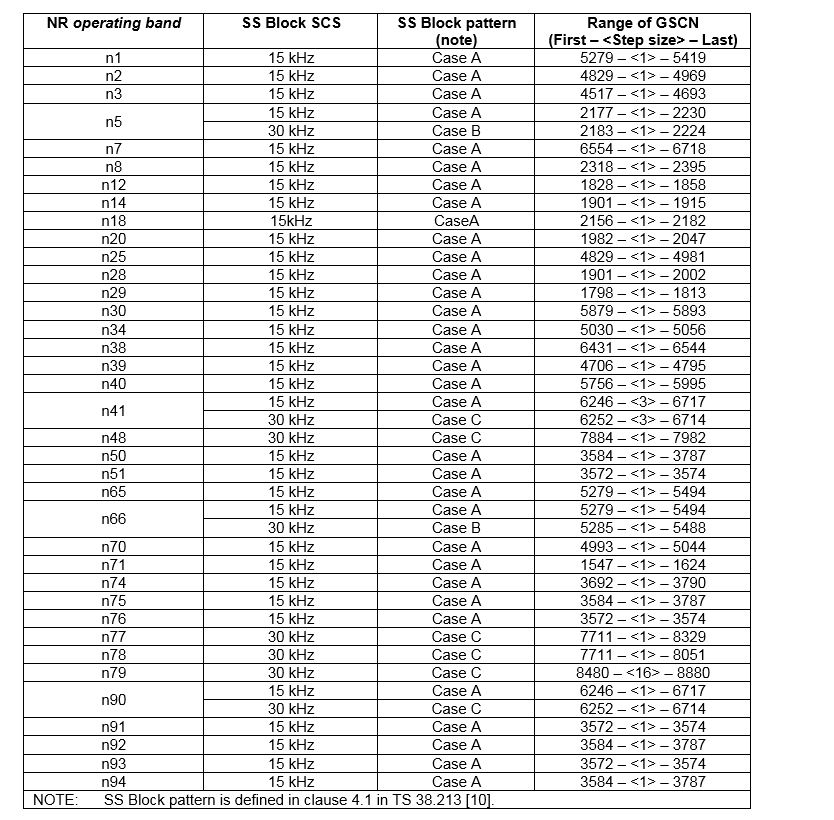
Table for Pattern/SCS to Symbol Mapping

UE reads PSS, SSS and PBCH information. PBCH provides MIB information. Following are the main content of MIB:
STEP 2: SIB1 Reading


UE reads PSS, SSS and PBCH information. PBCH provides MIB information. Following are the main content of MIB:
- DMRSTypeA-pos ==> Position for first DL DMRS position which is a type A DMRS
- subCarrierSpacingCommon ==> SCS for COREST 0
- ssb-SubcarrierOffset ==> kSSB , Frequency domain offset of CRB which is overlapping with lowest RB of SSB
- pdcchConfig-SIB1 ==> Provides frequency and symbol/slot information for CORESET 0 where SIB1 will be received. It contains two indexes
- ControlResourceSetZero ==> Index to table 13.1 => 13.10 in 38.213 that provides freq domain info for CORESET 0
- SerachSpaceZero ==> Index to Table 13.11 & 13.12 that provides the time domain info for CORESET 0.
- CORESET 0 contains DCI_1_0, which provides the downlink resources for PDSCH that carries SIB1.
- CORESET 0 is monitored on the two consecutive slots starting from slot index as mentioned below

Example 1: pdcchConfig-SIB 1 = 01010010 ==>
ControlResourceSetZero = 0101 = 5 , SearchSpaceZero = 0010 = 2.
As we are
operating in band n79, SCS for SSB = 30 KHz. subCarrierSpacingCommon = 30 KHz, Min BW = 5 or 10 MHz. Hence Table 13.4 will
be used.
From
Tables 13.4, Index = 5
(ControlResourceSetZero) ==>

Hence
for CORESET #0, Total No of RBs = 24, Offset will be defined wrt to CRB which
is overlapping with Lowest RB of SSB.
CORESET
# 0 will be 3 symbols long.
Here Pattern
= 1 and
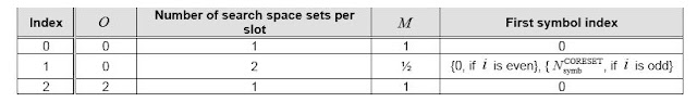
we are in FR1 range hence table 13.11 will be used for Time domain information. Index = 2
(SearchSpace Zero)

Based
on this O = 2, M =1, First Symbol Index = 0.
Now we have to calculate SFN and Slot from where CORESET 0 will be
present.
SlotIdx = (2 * 2 + i * 1)) mod 20
If i = SSB Idx = 1 ==> SlotIdx = 5
Below table indicates Coreset#0 location for each SSB index changes.
I (SSB Index)
|
Slot Idx = (O * 2 + I * M ) mod 20
|
SFN =
((O * 2 + I * M)/ 20 ) mod 2
|
0
|
4
|
0
|
1
|
5
|
0
|
2
|
6
|
0
|
3
|
7
|
0
|
4
|
8
|
0
|
5
|
9
|
0
|
6
|
10
|
0
|
7
|
11
|
0
|
Hence for SCS 30 KHz , pdcchConfig-SIB1 = 01010010 ==> CORESET 0 will be
transmitted on even no frames on slot starting from 4 (varying as per SSB Index). Starting Symbol
is symbol 0 and it is 3 symbol long.
=> what is the
DMRS configuration in CORESET #0 for PDCCH where DCI for SIB 1 will come
For
CORESET#0, 1CCE = 6 Reg where 1 REG =12 RE.
Out of this 12 RE, 3 REs are used
for DMRS and 9 for DCI. Every 4th
RE is DMRS signal.
With all this information, DCI will be received for SIB1 DL resources. Here are the DCI content for the same
PDCCH => DCI_1_0 with SI-RNTI indicating
PDSCH location for SIB 1.
DCI_1_0
for SI_RNTI comes with following information
Field Name
|
No Of Bits used
|
Description
|
DCI Format
Indicator
|
1
|
Indicates the DCI
format
|
Frequency Domain
Resource Assignment
|
Variable no of Bits depending on the CORESET
0 Size
|
Frequency domain
resources are indicated here in terms of start RB and no of RBs. Coded as
Type 1 i.e. RIV format. Starts with PRB 0 of CORESET#0.
|
Time Domain
Resource Assignment
|
4
|
Index to the Table
5.1.2.1.1-2 spec 38.214. It provides, Slot Offset (Ko, Start Symbol and
Length)
|
VRB-To-PRB-Mapping
|
1
|
|
MCS
|
5
|
|
Redundancy Version
|
2
|
|
System Information
Indicator
|
0 (SIB 1 is
present)
|
Once
DCI_1_0 is received, UE will move to the location in Time and frequency domain
as specified in DCI format and read SIB1.
STEP 3 : Random Access Procedure
SIB1-> ServingCellConfigCommonSIB->uplinkCommonConfigSIB->BWP-UplinkCommon->RACH-ConfigCommon
SIB
1 provides information on RACH parameters. Following are the information
Field Name
|
Description
|
ssb-perRACH-occasionAndCB-PreamblesPerSSB
|
Conveys two
information
|
prach-ConfigurationIndex
|
Index to the table
mentioned in spec 38.211 Table 6.3.3.2-3. Table provides following
information
|
msg1-FDM
|
Indicates many
RACH occasions are present in frequency domain for same time location.
|
msg1-FrequencyStart
|
Indicates the
offset to first RO in frequency domain from PRB 0
|
ra-ResponseWindow
|
Example
: prach-configurationIndex = 70 ,
ssb-perRACH-occasionAndCB-PreamblesPerSSB = one Half and n8 . It means 1
SSB will be present at 2 RACH occasions
msg1-FDM
= 2 i.e. 2 RO in frequency domain for same time location.
Msg1-FrequencyStart
= 3
Based
on prach-configurationIndex , following are the information retrieved from
Table 6.3.3.2-3

SFN for RO
= 1, 5, 9 …..
SubFrame
No on SFN = 9
No
Of RBs used for PRACH occasion will be calculated based on table 6.3.3.2-1 spec
38.211. e.g.
For
preamble Length = 139, FR1, SCS = 30 KHz, PRACH preamble SCS = 15 Khz.
Hence
No Of RBS = (139 * 15) / 30 * 12 = 834 6 RBs.
RA-RNTI
in RACh = 1 + s_id + 14 × t_id + 14 × 80 × f_id + 14 × 80 × 8 × ul_carrier_id
s_id : the index of the first OFDM symbol of the
specified PRACH (0 <= s_id < 14)
t_id : the index of the first slot symbol of
the specified PRACH in a system frame (0 <= t_id < 80)
f_id : the index of the the specified PRACH in
the frequency domain(0 <= s_id < 8)
ul_carrier_id : UL carrier used for Msg1
transmission (0 = normal carrier, 1 = SUL carrier)
- Once RACH is received, gNB transmits DCI_1_0 with downlink resources scrambled with RA-RNTI f for sending Random Access response (RAR) message. UE is assigned with UL resources in RAR message.
DCI_1_0
with RA-RNTI =
Field Name
|
No Of Bits used
|
Description
|
Frequency Domain
Resource Assignment
|
Variable no of Bits depending on the CORESET
0 Size
 |
Frequency domain
resources are indicated here in terms of start RB and no of RBs. Coded as
Type 1 i.e. RIV format. Starts with PRB 0 of CORESET#0.
|
Time Domain
Resource Assignment
|
4
|
Index to the Table
5.1.2.1.1-2 spec 38.214. It provides, Slot Offset (Ko, Start Symbol and
Length)
|
VRB-To-PRB-Mapping
|
1
|
|
MCS
|
5
|
|
TB Scaling
|
2
|
|
Reserved
|
16 bits
|
DCI
size for above case where #CORESET 0 size = 24 octets
Frequency
Domain size = log2 ((24 * 25)/2) = 8.22 = 9 bits
Total
DCI_1_0 size = 9 + 4 + 1 + 5 + 2 + 16 =
37 bits
- Once RAR is received at this location, it will assign the position for PUSCH where it can transmit msg3 (RRC Setup Request).
How to find PDSCH/PUSCH location based on the DCI fields
DCI format brings the index of Resource allocation which is assigned in RRCReconfiguration message or for initial serach it will be an index to tables mentioned in 38.214 tables 6.1.2.1.1
FrequencyDomainResourceAllocation: Indicates, startRB and NoOfRBs allocated for PUSCH/PDSCH.
TimeDomainResourceAllocation: It will be used to find slot & symbol locations for PUSCH/PDSCh. Below is the description, how it is interpreted:
PUSCH-TimeDomainResourceAllocation
::= SEQUENCE {
k2
INTEGER(0..32)
OPTIONAL, -- Need S
mappingType ENUMERATED {typeA,
typeB},
startSymbolAndLength INTEGER (0..127)
}
PDSCH-TimeDomainResourceAllocation
::= SEQUENCE {
k0
INTEGER(0..32)
mappingType ENUMERATED {typeA,
typeB},
startSymbolAndLength INTEGER (0..127)
}
K0/k2 è
Slot Offset between PUSCH/PDSCH and DCI reception
MappingType : DMRS positions will be identified.
StartSymbolAndLength: Indicates start symbol and length.
This will be interpreted as mentioned here
Slot Idx will be calculated as

where, n = Slot where DCI is received.
K0 is slot offset for PUSCH. For PDSCH, it will be K2.
SLIV calculation:


Comments
Post a Comment